Control MESHLE Bluetooth Mesh Devices from a WAGO PLC via Modbus TCP (CODESYS Guide)
MESHLE devices are wirelessly connected over MESHLE Bluetooth Mesh — a proprietary, offline-first mesh that keeps your lighting, sensors, and actuators running without the cloud. The MESHLE Gateway bridges that wireless network into the rest of your building’s infrastructure, exposing the mesh over an open API surface — REST, MQTT, Modbus TCP/IP, and BACnet™ — so any wired control system you already run can read and control it.
This guide walks the Modbus bridge end to end. You’ll configure a WAGO CC100 PLC as a Modbus TCP client that reads from and writes to wirelessly connected MESHLE devices through the gateway’s holding registers, then exposes those values as IEC variables in a CODESYS 3.5 project. Modbus TCP is configured entirely within the CODESYS device tree — no additional tools required.
It’s written for building-automation and BMS integrators and for OEM engineers who need wireless MESHLE lighting under PLC control. The worked example uses a multichannel dimmer (Out32) at unit address 1, which exposes 4 output channels and a power state over Modbus TCP holding registers — but the same pattern bridges every MESHLE device type on the mesh into your wired control system.
Overview
This guide documents the full process of bridging a wirelessly connected MESHLE Bluetooth Mesh network into a wired control system: setting up a WAGO CC100 as a Modbus TCP client that reads from and writes to MESHLE Gateway devices, and exposing those values as IEC variables in a CODESYS 3.5 project.
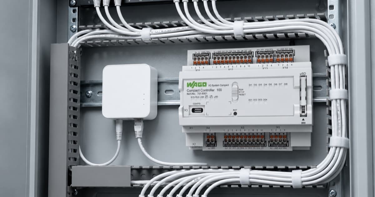
The sample device used throughout is the WAGO CC100 (751-9301). Any other WAGO controller that supports CODESYS 3.5 follows the same process — only the device selection step when creating the CODESYS project differs.
The CC100 acts as the Modbus TCP client and the MESHLE Gateway acts as the server. The CODESYS Modbus TCP device driver handles all polling automatically once channels are configured. Your PLC program simply reads from and writes to the mapped array variables.
Prerequisites
Have the following hardware and software in place before you start.
Hardware
- WAGO CC100 (751-9301) on firmware 6.4.6.x or later (the sample device used here — any compatible WAGO controller supporting CODESYS 3.5 works)
- MESHLE gateway with Modbus TCP server enabled on port 502
- PC on the same network as the CC100 and the MESHLE gateway
Software
- CODESYS 3.5 SP22 Patch 1 or later
- WAGO Devices and Libraries package 2.0.9.2 or later (installed via CODESYS Installer)
MESHLE Gateway requirements
- Modbus TCP server running on port 502
- Unit address of the target device is 1
- Register map version 1 layout (fixed device bank starting at register 256, device stride 50)
Register Map Reference (Out32 Device, Unit Address 1)
The MESHLE gateway uses a fixed register layout. A device’s bank starts at 256 + (unit address − 1) × 50. For unit address 1, the device base is therefore register 256.
Status registers (read, FC03, starting at offset 256)
| Register Offset | Address | Name | Description |
|---|---|---|---|
| 10 | 266 | STATUS_FLAGS | bit0 = power actual, bit2 = device online |
| 23 | 279 | OUT32_CH1 | Channel 1 actual, 0..1000 (×10 percent) |
| 24 | 280 | OUT32_CH2 | Channel 2 actual, 0..1000 (×10 percent) |
| 25 | 281 | OUT32_CH3 | Channel 3 actual, 0..1000 (×10 percent) |
| 26 | 282 | OUT32_CH4 | Channel 4 actual, 0..1000 (×10 percent) |
Command registers (write, FC16, starting at offset 286)
Command base: 256 + 30 = 286
| Register Offset | Address | Name | Description |
|---|---|---|---|
| 0 | 286 | CMD_FLAGS | bit0 = power on/off |
| 7 | 293 | CMD_OUT32_CH1 | Channel 1 target, 0..1000 (×10 percent) |
| 8 | 294 | CMD_OUT32_CH2 | Channel 2 target, 0..1000 (×10 percent) |
| 9 | 295 | CMD_OUT32_CH3 | Channel 3 target, 0..1000 (×10 percent) |
| 10 | 296 | CMD_OUT32_CH4 | Channel 4 target, 0..1000 (×10 percent) |
Important: All register values use a ×10 scale. A brightness of 75% is stored as register value 750. Always divide reads by 10 and multiply writes by 10 in your PLC program.
Part 1: CODESYS Project Setup
1.1 Create a New Project
- Open CODESYS and go to File > New Project
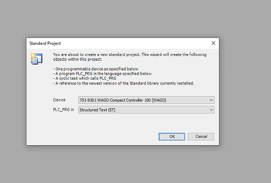
- Select Standard Project and click OK
- When prompted to select a device, search for 751-9301 and select WAGO Compact Controller 100
- Set the programming language to Structured Text (ST)
- Click OK and save the project with Ctrl+S
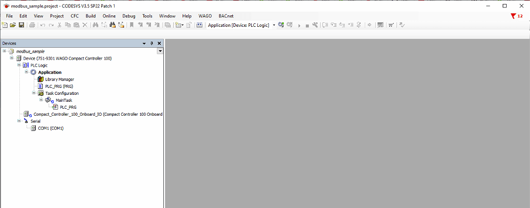
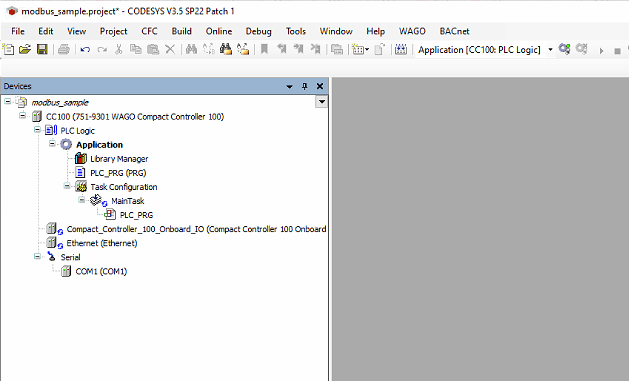
The project opens with the default device tree. Note the device is named Device at this stage.
1.2 Rename the Device
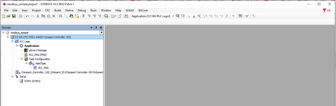
The device must be named CC100 in the device tree for consistency and to avoid issues with certain WAGO libraries.
- Right-click the top-level device node (Device (751-9301 WAGO Compact Controller 100))
- Select Properties
- Change the name to CC100
- Click OK
1.3 Add Ethernet Adapter
The Modbus TCP Client must sit under an Ethernet adapter node. This represents the CC100’s network interface.
- Right-click CC100 in the device tree
- Select Add Device...
- Expand Ethernet Adapter
- Select Ethernet
- Click Add Device and close the dialog
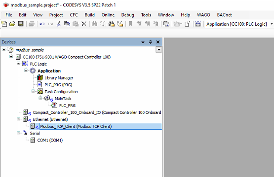
1.4 Add Modbus TCP Client
- Right-click Ethernet (Ethernet) in the device tree
- Select Add Device...
- Expand Fieldbuses > Modbus
- Expand Modbus TCP Client
- Select Modbus TCP Client (CODESYS, version 4.5.0.0)
- Click Add Device and close the dialog
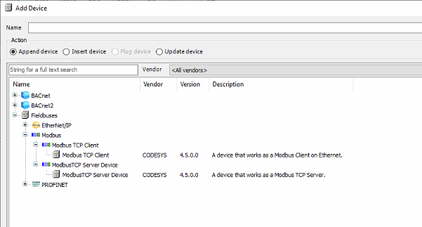
Note: CODESYS names these devices Modbus TCP Client and Modbus TCP Server — not Master/Slave as some older documentation does. The Client is the CC100 (the Modbus master). The Server represents the remote device being polled (the MESHLE gateway).
1.5 Add Modbus TCP Server
- Right-click Modbus_TCP_Client in the device tree
- Select Add Device...
- Expand Fieldbuses > Modbus > Modbus TCP Server
- Select Modbus TCP Server (CODESYS, version 4.5.0.0)
- Click Add Device and close the dialog
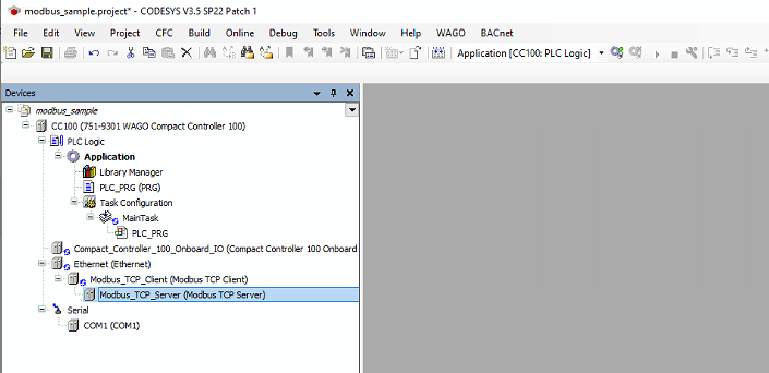
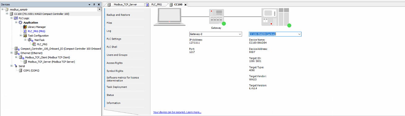
The device tree now shows the full structure:
CC100
└── Ethernet (Ethernet)
    └── Modbus_TCP_Client (Modbus TCP Client)
        └── Modbus_TCP_Server (Modbus TCP Server)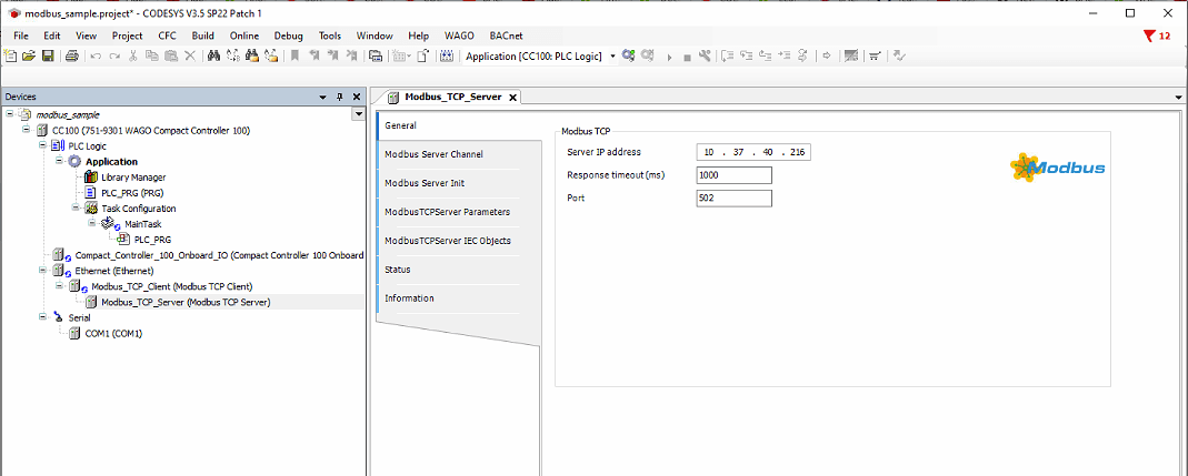
Part 2: Modbus TCP Server Configuration
2.1 Configure Gateway IP and Port
- Double-click Modbus_TCP_Server in the device tree
- The General tab opens
- Set Server IP address to the IP address of your MESHLE gateway
- Set Response timeout (ms) to 5000
- Set Port to 502
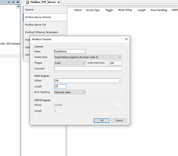
2.2 Configure Read Channel
- Click the Modbus Server Channel tab
- Click Add Channel
- Configure the channel as follows:
- Name: ReadStatus
- Access type: Read Holding Registers (Function Code 3)
- Trigger: Cyclic
- Cycle time (ms): 100
- READ Register Offset: 256
- Length: 27
- Error handling: Keep last value
- Click OK
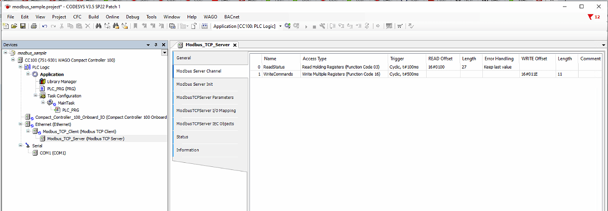
2.3 Configure Write Channel
- Still on the Modbus Server Channel tab, click Add Channel again
- Configure the channel as follows:
- Name: WriteCommands
- Access type: Write Multiple Registers (Function Code 16)
- Trigger: Cyclic
- Cycle time (ms): 500
- WRITE Register Offset: 286
- Length: 11
- Click OK
Both channels should now appear in the channel list:
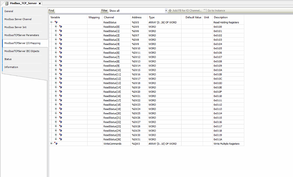
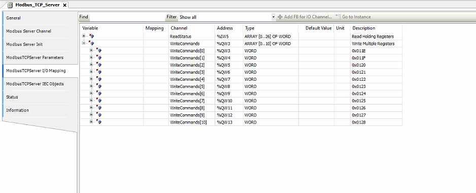
2.4 Assign Global Variables in I/O Mapping
- Click the ModbusTCPServer I/O Mapping tab
- You will see the two channel arrays listed with empty Variable columns
- Click the empty Variable cell on the top-level ReadStatus row
- Type ReadStatus and press Enter
- Do the same for the top-level WriteCommands row — type WriteCommands and press Enter
- Save with Ctrl+S
A mapping indicator appears in the Mapping column, confirming CODESYS has created the global variables bound to the channel arrays.
Note: Typing a plain name (no dot prefix) in the Variable column creates an implicit global variable automatically. These variables are then accessible directly in PLC_PRG without any namespace prefix.
2.5 Set Unit ID
This is a critical step. The Unit-ID must match the Modbus unit address of the target device on the MESHLE gateway. A mismatch causes the gateway to reject all requests, leading to repeated connect/disconnect cycles that eventually exhaust the gateway’s connection limit.
- Click the ModbusTCPServer Parameters tab
- Locate Unit-ID
- Set it to the unit address of your device — 1 in this example
- Also set ResponseTimeout to 5000
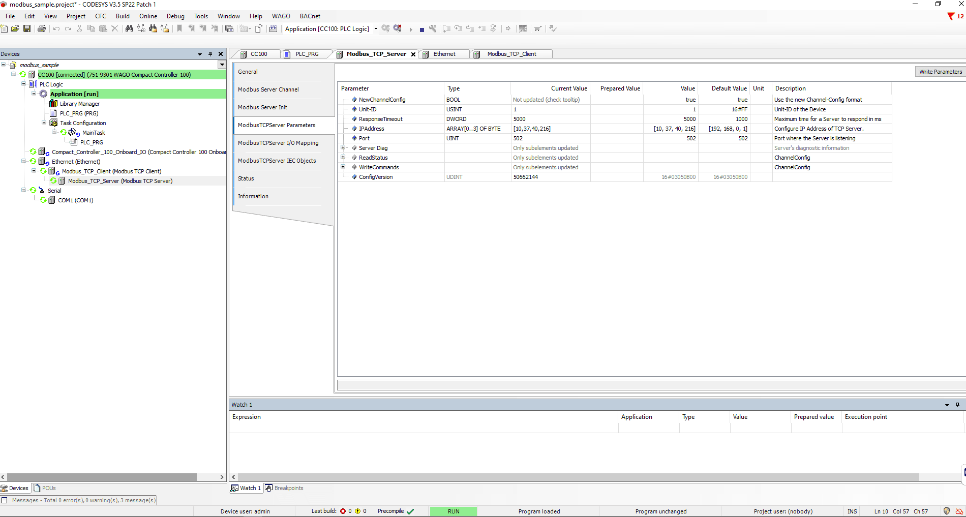
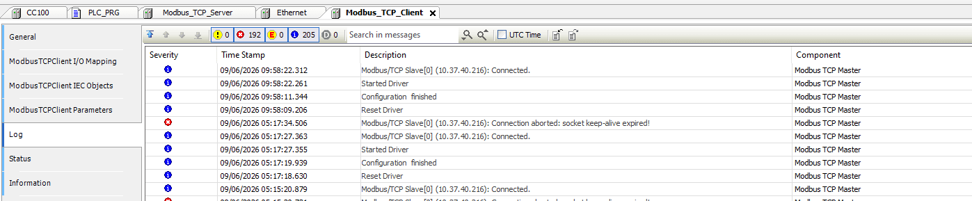
Important: The default Unit-ID is 255. If you leave it at the default while your device has a different unit address, the gateway rejects all requests. The symptom is a repeated “Connected” / “Connection aborted: socket keep-alive expired” loop in the Modbus TCP Client log, with an ever-increasing error counter. Always set Unit-ID to match your target device.
Part 3: Configure Ethernet Interface
The Ethernet adapter must be bound to the CC100’s correct physical network interface.
- Double-click Ethernet (Ethernet) in the device tree
- Click Browse... next to the Network interface field
- Select br0 — this is the CC100’s bridged network interface
- Do NOT check Adjust operating system settings — this would overwrite the CC100’s network configuration
Note: The default network interface shown may be a 192.168.x.x address. Always verify the interface is br0 on the correct subnet before going online.
Part 4: PLC Program
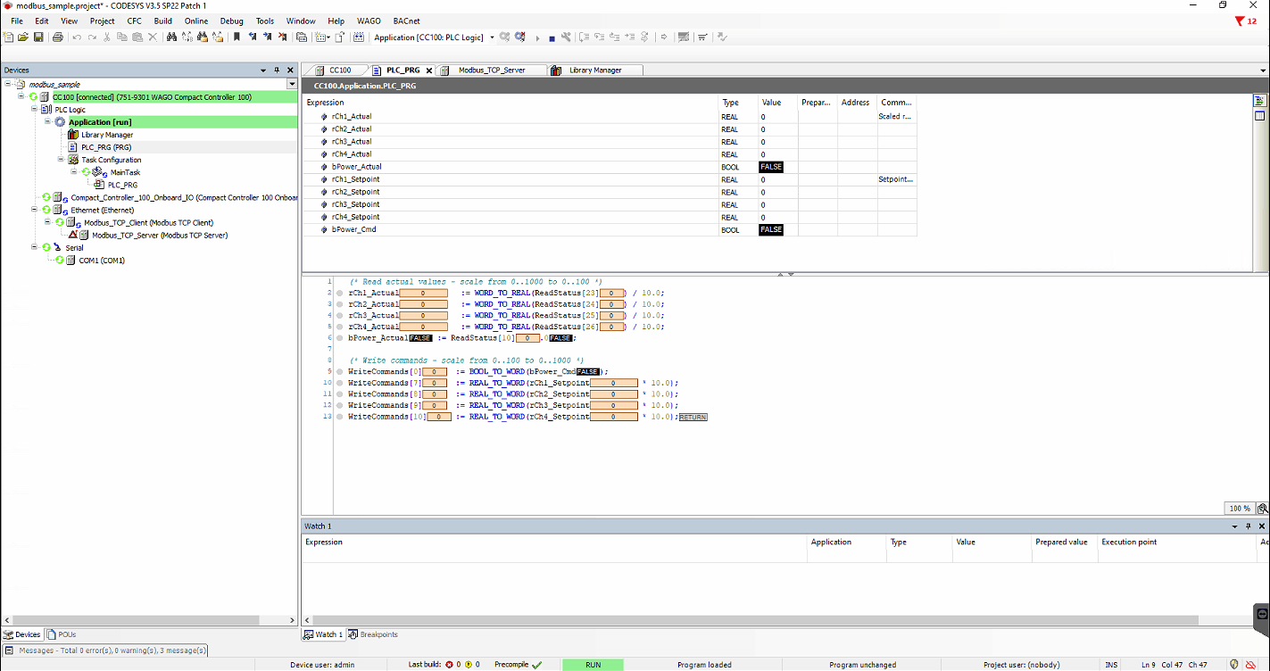
Open PLC_PRG. The editor has two panels: the declaration section at the top and the body at the bottom.
Declaration
PROGRAM PLC_PRG
VAR
    (* Actual values read from device - scaled 0..100 % *)
    rCh1_Actual     : REAL;
    rCh2_Actual     : REAL;
    rCh3_Actual     : REAL;
    rCh4_Actual     : REAL;
    bPower_Actual   : BOOL;
    bOnline         : BOOL;

    (* Commands to send to device *)
    bPower_Cmd      : BOOL;
    rCh1_Setpoint   : REAL;
    rCh2_Setpoint   : REAL;
    rCh3_Setpoint   : REAL;
    rCh4_Setpoint   : REAL;
END_VAR
Body
(* --- Read actual state from device --- *)
(* Registers return 0..1000, divide by 10 to get 0..100 % *)
rCh1_Actual   := WORD_TO_REAL(ReadStatus[23]) / 10.0;
rCh2_Actual   := WORD_TO_REAL(ReadStatus[24]) / 10.0;
rCh3_Actual   := WORD_TO_REAL(ReadStatus[25]) / 10.0;
rCh4_Actual   := WORD_TO_REAL(ReadStatus[26]) / 10.0;
bPower_Actual := ReadStatus[10].0;    (* bit 0 = power on/off *)
bOnline       := ReadStatus[10].2;    (* bit 2 = device reachable *)

(* --- Send commands to device --- *)
(* Power: sent as a dedicated power command, independent of channels *)
WriteCommands[0] := BOOL_TO_WORD(bPower_Cmd);

(* Channels: sent independently, multiply by 10 to get 0..1000 register scale *)
WriteCommands[7]  := REAL_TO_WORD(rCh1_Setpoint * 10.0);
WriteCommands[8]  := REAL_TO_WORD(rCh2_Setpoint * 10.0);
WriteCommands[9]  := REAL_TO_WORD(rCh3_Setpoint * 10.0);
WriteCommands[10] := REAL_TO_WORD(rCh4_Setpoint * 10.0);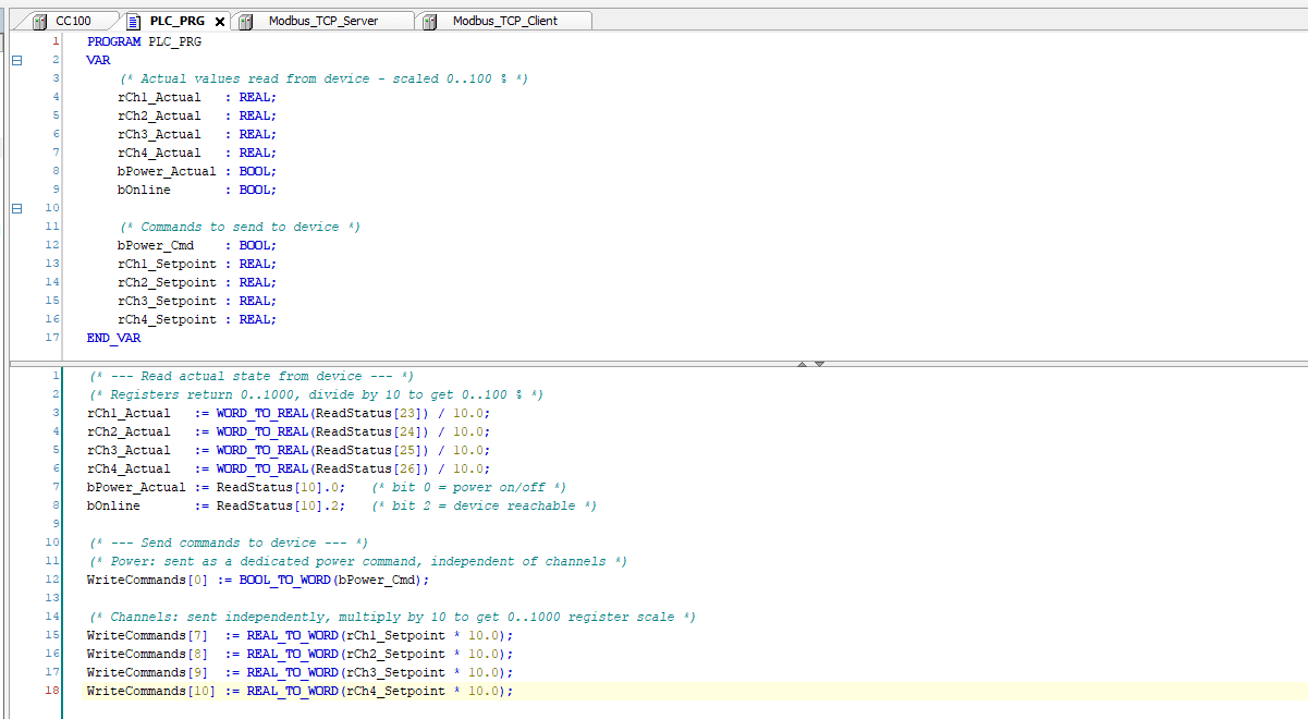
The array indices map directly to register offsets within the configured channel:
ReadStatus[23]= register offset 23 within the device block = OUT32_CH1 actualWriteCommands[7]= register offset 7 within the command section = CMD_OUT32_CH1
Part 5: Connect and Download
5.1 Fix Build Errors
On the first build, you may see 41 errors referencing DED.DEVICE_STATE. These come from the Compact_Controller_100_Onboard_IO node and are caused by two missing system libraries. They are not related to your Modbus code.
To fix:
- Double-click Library Manager
- Click Download Missing Libraries in the toolbar
- Two libraries will be listed as missing:
- Redundancy Implementation 3.5.21.0
- CAA Device Diagnosis 3.5.21.0
- Ensure both are checked and click Download
- Build again with F11 — errors should clear
5.2 Go Online
- Confirm the CC100 physical RUN/STOP switch is in the RUN position
- Go to Online > Login
- When prompted about no active path, click Yes to scan the network
- Select CC100 from the scan results and click OK
- If a device version mismatch warning appears, click OK to proceed
- When prompted to download, check Update boot application and click Yes
- Press F5 to start the application
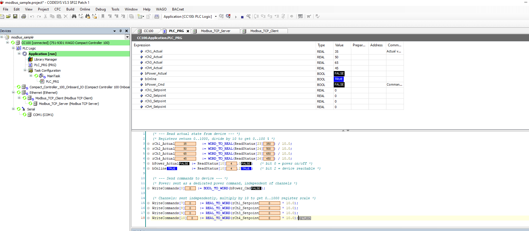
Part 6: Reading and Writing Values
Reading Values
Once online and running, the PLC_PRG watch panel shows live values. The rCh1_Actual through rCh4_Actual variables update automatically from the MESHLE device channels via the ReadStatus channel. bOnline confirms the device is reachable.
Writing Values
To write a value from CODESYS to the MESHLE device, update the setpoint variables and write them via the debug window.
How to write in the debug window
- In the watch panel, click the Prepared Value column next to rCh1_Setpoint
- Enter the desired value (0..100 representing percent)
- Do the same for any other setpoints and bPower_Cmd
- Click Write Values in the debug toolbar (or press Ctrl+F7)
- The values are scaled by 10, written to WriteCommands, and sent to the device via FC16
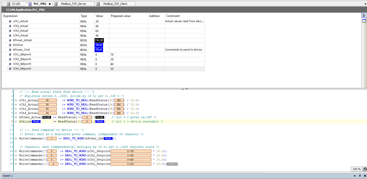
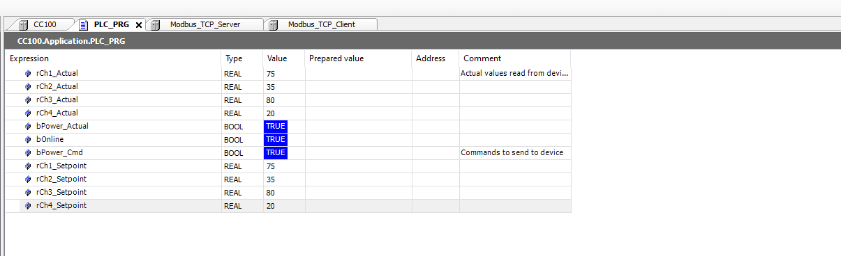
Note: The setpoint variables start at 0 and only take effect when written via the debug window or set programmatically. The actual values reflect the current device state and update independently.
Known Issues and Troubleshooting
Repeated Connect / Disconnect Loop
Symptom: The Modbus TCP Client log shows a repeated cycle of “Connected” followed immediately by “Connection aborted: socket keep-alive expired”. The error counter increments rapidly. Other Modbus clients on the network may also get blocked.
Cause: The Unit-ID on the Modbus TCP Server does not match the unit address of the target device on the MESHLE gateway. The gateway rejects all requests and the CODESYS driver repeatedly reconnects without properly closing the previous socket. The gateway supports a maximum of 3 concurrent connections, so slots fill up quickly.
Fix: Go to the ModbusTCPServer Parameters tab and set Unit-ID to match the unit address of your target device. Stop the application (Online > Stop), log out (Online > Logout), wait 30 to 60 seconds for the gateway to release stale connections, then log in and restart.
Build Errors: DED.DEVICE_STATE Not Defined
Cause: The CAA Device Diagnosis library is missing from the CODESYS installation. This library is required by the CC100’s onboard IO device node.
Fix: In Library Manager, click Download Missing Libraries. Install both Redundancy Implementation and CAA Device Diagnosis when prompted.
Values Showing 0 After Going Online
Cause: Either the Ethernet adapter is bound to the wrong network interface, or the Unit-ID does not match the target device.
Fix: Check the Ethernet adapter is set to br0 on the correct subnet. Verify the Unit-ID in ModbusTCPServer Parameters matches your device. Check the Modbus TCP Client log for connection errors.
No Separate Download Step Required
Modbus TCP requires only a single download operation — Online > Login in CODESYS. All Modbus configuration is embedded in the CODESYS project and downloaded with it.
Beyond Modbus — every device, every protocol
The read/write pattern you built here for one multichannel dimmer applies to every device on your MESHLE Bluetooth Mesh network. Sensors expose registers you only read; actuators like single-channel dimmers, HCL, and HSV expose registers you read and write — same channel workflow, just different register counts. Once the MESHLE Gateway is on the network, your whole wirelessly connected mesh is addressable from any wired control system as a standard Modbus TCP server.
Modbus TCP is one of four open paths off the gateway. If your stack isn’t Modbus-based, the same MESHLE devices are reachable over REST API, MQTT, and BACnet™. Building a BMS or PLC integration around MESHLE lighting? Talk to us about your project — we support integrators and OEMs through the full design-in.
Deep dive: DALI lighting control on Bluetooth Mesh — DALI-2/D4i compatible, up to 4 addresses per node, no rewiring.
Further reading
- Bridge the same WAGO PLC to MESHLE over BACnet™ instead of Modbus
- MESHLE Gateway: one mesh, open APIs (REST, MQTT, Modbus, BACnet™)
- How MESHLE LED drivers fit into a smart lighting ecosystem
- Connect MESHLE devices to Node-RED over local MQTT
- Why MESHLE smart lighting works offline-first
- Contact MESHLE about a BMS or PLC integration
BACnet™ is a trademark of ASHRAE.